Hi everyone!!
I would like to make a short parenthesis in order to propose a small practical training, for those who read the PWM post and liked it, but don't actually know how to apply it.
Thus, I am going to explain how to light progressively an LED by using PWM signals generated by an Arduino UNO PCB (by the timer).
Note that the PWM signal is going to feed a light instead of a DC Motor. Using a LED, the frequency doesn't matter because LED's don't generate any noise. However, I am going to demonstrate how to change it for those who want to feed a DC motor using a 4KHz PWM with Arduino.
PREPARATION
The material list which you need to have to follow this post is below.
- Arduino UNO Board

- LED and 300ohm resistance.
In the picture below you can see the resistance colors, so you can chose the correct one.

- Breadboard

- Wires

These wires are nice for testing, I recommend you guys should buy them!!
METHODOLOGY
- You should connect the components as described in the next picture.
Please, note that the red wires are not needed because they are not used. In addition the black ones are going to be green in the video example.
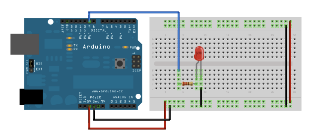 |
| Taken from the fading example at www.arduino.cc |
WARNING!!! This post is an example of generating PWM signals, so make sure that the blue wire is connected at a PWM output.
- Once the hardware is prepared, we can start writing the software. Below you will find a software which uses the timer for generating the PWM signal.
The line in yellow is used to change the timer frequency to 4 KHz. Later on in this post you will see pictures taken by the oscilloscope.
/*
TimerPWm
This example shows how to fade an LED using the timer.
The circuit:
* LED attached from digital pin 9 to ground.
Created June 2013
By Oriol Parera Fiestas
This example code is in the public domain.
*/
int ledPin = 9; // LED is connected to digital pin 9
int brightness = 0; /* from 0 to 1023*/
bool growing;
void setup() {
TCCR1B = TCCR1B & 0b11111000 | 0x02; //4KHz
pinMode(ledPin, OUTPUT); // sets the pin as output
analogWrite(ledPin, 0); // analogWrite values from 0 to 255
growing = true;
}
void loop() {
brightness = growing? brightness+5:brightness-5;
if (brightness > 255)
{
brightness = 255;
growing = false;
}
if (brightness < 0)
{
brightness = 0;
growing = true;
}
analogWrite(ledPin, brightness);
delay (30);
}
- Flash the Arduino memory and enjoy!!
EXPECTED RESULTS
A picture is worth a thousand words, so below is a video were you can see the results that should be achieved.
If you achieved it, congratulations!!! :D If not, write a comment and I will be very happy to help you!!
Finally, the next pictures show the signal generated at the PIN 9. The first one, which is around 512 KHz, is taken without changing the default frequency (the yellow line was commented). In contrast, the second one changes the frequency to 4KHz.


Please, let me know your experience by leaving your comments!!
I look forward to seeing you on my next post!!!
No comments:
Post a Comment