Tuesday, 18 June 2013

Electronics: Moving the train (Part II) - H-Bridge

Hi you all guys,

After reading the PWM signals theorical and practical posts I hope that you all know perfectly how to control DC Motor's velocity. Thus, let's move forward and see how we could control the direction as well.

The pictures below show how the H-Bridge concept works. Note that when transistors S2 and S3 are enabled, electricity goes through the motor from its right side to its left one and the motor therefore moves forward. In contrast, when  transistors S1 and S4 are enabled instead, electricity goes through the motor from its left side to its right one and the motor then moves backward.


Thus, the DC Motors directions may be controlled by enabling and disabling transistors.

However, there are easier solutions such the L298, which is an integrated chip that internally has two h-bridges and therefore provides full control of 2 motors. Those who don't know about it yet, below is a link where you will find its datasheet.:


In addition, there are some PCBs that are already prepared for being used with this L298. In the picture below you will see the PCB which I used:


As you can see, on the left side of the PCB are placed the inputs and on the right side are the outputs. Specifically, ENA, IN1 and IN2 provide the control for the MotorA while the ENB, IN3 and IN4 provides the control for the MotorB. The ENA and ENB receives a 5V PWM signal each and the IN1-IN2 and ÍN3-N4 pairs work as told in the true table below.

 IN1/IN3    IN2/IN4  Motor status
´ 0               0              Stopped
  0               1              Move forward
  1               0              Move backward
  1               1              Emergency break

Unfortunately, the L298 is prepared for current peaks lower than 2,5A on each channel and 3A on both channels working in parallel. The DC Motor, which my trains use, may consume current peaks higher than 3A, so by the moment I am using another PCB which is prepared for current peaks around 10A. You will find a picture of this PCB below.


Please, leave your comments!!!

See you guys!

Sunday, 9 June 2013

THE LIGHTHOUSE - TRaiNhaCKs workshop (I)

Hi everyone!!

I would like to make a short parenthesis in order to propose a small practical training, for those who read the PWM post and liked it, but don't actually know how to apply it.

Thus, I am going to explain how to light progressively an LED by using PWM signals generated by an Arduino UNO PCB (by the timer).

Note that the PWM signal is going to feed a light instead of a DC Motor. Using a LED, the frequency doesn't matter because LED's don't generate any noise. However, I am going to demonstrate how to change it for those who want to feed a DC motor using a 4KHz PWM with Arduino.

PREPARATION 

The material list which you need to have to follow this post is below.
  • Arduino UNO Board


  • LED and 300ohm resistance.
In the picture below you can see the resistance colors, so you can chose the correct one.


  • Breadboard

  • Wires

These wires are nice for testing, I recommend you guys should buy them!!

METHODOLOGY 
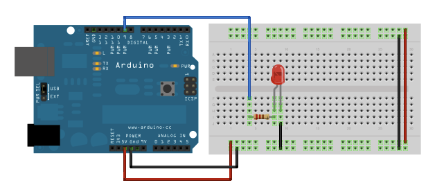
  • You should connect the components as described in the next picture. 
Please, note that the red wires are not needed because they are not used. In addition the black ones are going to be green in the video example.
Taken from the fading example at www.arduino.cc
WARNING!!! This post is an example of generating PWM signals, so make sure that the blue wire is connected at a PWM output.
  • Once the hardware is prepared, we can start writing the software. Below you will find a software which uses the timer for generating the PWM signal.
The line in yellow is used to change the timer frequency to 4 KHz. Later on in this post you will see pictures taken by the oscilloscope.

/*
 TimerPWm


 This example shows how to fade an LED using the timer.


 The circuit:

 * LED attached from digital pin 9 to ground.


 Created June 2013

 By Oriol Parera Fiestas


 This example code is in the public domain.


 */


int ledPin = 9;    // LED is connected to digital pin 9
int brightness = 0; /* from 0 to 1023*/


bool growing;


void setup()  {   
  TCCR1B =  TCCR1B & 0b11111000 | 0x02; //4KHz
  
  pinMode(ledPin, OUTPUT);  // sets the pin as output
  
  analogWrite(ledPin, 0);  // analogWrite values from 0 to 255
  growing = true;


void loop()  { 
  brightness = growing? brightness+5:brightness-5;
  
  if (brightness > 255) 
  {
     brightness = 255;
     growing = false;
  }
  
  if (brightness < 0) 
  {
     brightness = 0;
     growing = true;
  }
  
  analogWrite(ledPin, brightness);
  delay (30);
}

  • Flash the Arduino memory and enjoy!!


EXPECTED RESULTS

A picture is worth a thousand words, so below is a video were you can see the results that should be achieved.


If you achieved it, congratulations!!! :D If not, write a comment and I will be very happy to help you!!

Finally, the next pictures show the signal generated at the PIN 9. The first one, which is around 512 KHz, is taken without changing the default frequency (the yellow line was commented). In contrast, the second one changes the frequency to 4KHz.


Please, let me know your experience by leaving your comments!!

I look forward to seeing you on my next post!!!

Tuesday, 4 June 2013

Electronics: Moving the train (Part I) - PWM Signal

Hi again you all guys, how are you doing?

When I first began thinking of the electronics design, I understood that my first challenge was going to be “moving the train”. Thus, this post is aimed at those who don’t know how to move DC motors using a microcontroller. Anyway, my purpose is not explaining it in depth, but to provide links where you can find out more details.

So far there are two things related to DC Motors that need to be controlled; velocity and direction. The velocity is controlled by a transistor which receives a PWM signal and the direction is controlled by four transistors disposed in H-bridge.

This post expects to give some notions of PWM signals. In addition, the next one will detail the H-Bridge issues.
  • PWM signals and DC Motors

PWM signals can be used in several applications. For instance, they can offer a digital way of driving DC motors. As you know, DC motors behavior is as described below.
  1. When the motor receives no power, it just stays stopped. In contrast, if the motor is fed with 24V DC, the train travels at the fastest movement speed.
  2.  In the range between 0V and 24V: The higher is the applied voltage, the faster the motor spins.
Note that motors are fed with 24V DC in my case.


In contrast, transistors can be just in two different states: opened or closed. It means that transistors provide the voltage given by the power supply when it is connected or just zero when it is disconnected.

The key concept of using PWM signals is that motors can’t vary their velocity instantly, so the provided voltage is exactly the average voltage. In my case, the working frequency of this signal is 4 KHz.

In addition, the motor speed is given by the time which the signal is 24V versus the time which it is 0V. The time which the motor is provided with 24V in each period is called the duty cycle.


For more information related to PWMs, here is a link: http://en.wikipedia.org/wiki/Pulse-width_modulation
  • Generating a PWM signal
PWM signals can be generated basically in two ways; by software and by hardware. The former is not the best way, because microcontrollers are not powerful processors and we therefore need them to be free in order to execute other tasks.  In contrast, the latter is a very good way of generating PWM signals, because the software just spends the time needed to configure the hardware and then it stays free to execute whatever is needed.

On the other hand, sometimes there aren't any available hardware resources and then the PWM signal has to be generated by software. 

In my case, which I will explain later on this blog, I use Arduino and a STM8S microcontrollers. Both microcontrollers are able to generate PWM signals by hardware, which in my case is being 4 KHz.

Specifically in the case of Arduino, a basic high-level library is provided and therefore generating PWM signals is really easy. The only thing to be considered is that the default PWM signal works around 512Hz, which is a very low frequency and induces noises to the motor.

For those who are using Arduino, you will find an explanation on how to change its timer configuration in order to vary the PWM signal frequency: http://arduino.cc/en/Tutorial/SecretsOfArduinoPWM

Here are exposed all the possible combinations of settings which can be set to the timers frequency: 

Pins 5 and 6: controlled by Timer 0
etting Divisor Frequency
S0x01 1 62500
0x03 64 976.5
0x02 8 7812.5 625
5 0x05 1024 61.0351
0x04 256 244.1406 25625 TCCR0B = TCCR0B & 0b11111000 | <setting>;
Pins 9 and 10: controlled by timer 1
etting Divisor Frequency
S0x01 1 31250
0x03 64 488.2
0x02 8 3906.2 58125 0x04 256 122.0703125
R1B = TCCR1B & 0b11111000 |
0x05 1024 30.517578125 TC C<setting>;
Pins 11 and 3: controlled by timer 2
etting Divisor Frequency
S0x01 1 31250
0x03 32 976.5
0x02 8 3906.2 5625 0x04 64 488.28125
6 256 122.0703125 0
0x05 128 244.140625 0x
0x07 1024 30.517578125

For instance, the next line sets the Timer2 to 4KHz.


TCCR2B = TCCR2B & 0b11111000 | 0x02; //4KHz

I'll see you on my next post

Friday, 24 May 2013

Els ferrocarrils de la terrassa

Hi all!!!

I hope you guys enjoy this blog. The story starts as follows...

It all began a few years ago when my father, who loves trains, decided to build his own model on his terrace. He started by drilling a hole in the wall (yes, a really big hole!!), which allowed the train to go from inside to the terrace. After that, he built stations, bridges and binds step by step... At last it all started to look like the wonderful model which today it is!!

Here are some videos that can be seen to understand what it was like. Next, I am proud to introduce Mr Joanet, who is going to guide you all with a small visit to the circuit!!


Surprised by my father's initiative, which actually I loved, I decided to help him. Later, I became the "electronics and firmware responsible" (to say so...) :) So, I started thinking on some hardware and software to control all of that. And somehow, my project had already started!!!

The aim of this blog is to share the challenges and the issues faced during the technical development.

I'll see you people on my next post!!